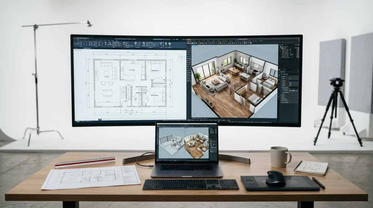
Every 2D floor plan to 3D model conversion looks simple on paper — trace the walls, push them up, add a roof. Then you open your render preview and the corners have light bleeding through them, the wood floor tiles look like they were stretched over a beach ball, and something about the proportions just feels off, even though you followed the plan exactly. In our studio, we run this conversion constantly for architectural visualization, real estate marketing, and interactive walkthroughs, and the pattern is always the same: the extrusion step takes minutes. Everything before it and after it is where the real work — and the real risk of a bad render — actually lives.
This isn’t a tutorial on which button to click in which software. It’s a breakdown of the decisions that determine whether your final render looks like a real space or like a viewport screenshot with a sky background pasted behind it. The logic holds whether you’re producing a single hero still, a full walkthrough animation, or a lightweight model for a web-based property viewer.
What “2D Floor Plan to 3D Model” Really Means for Rendering
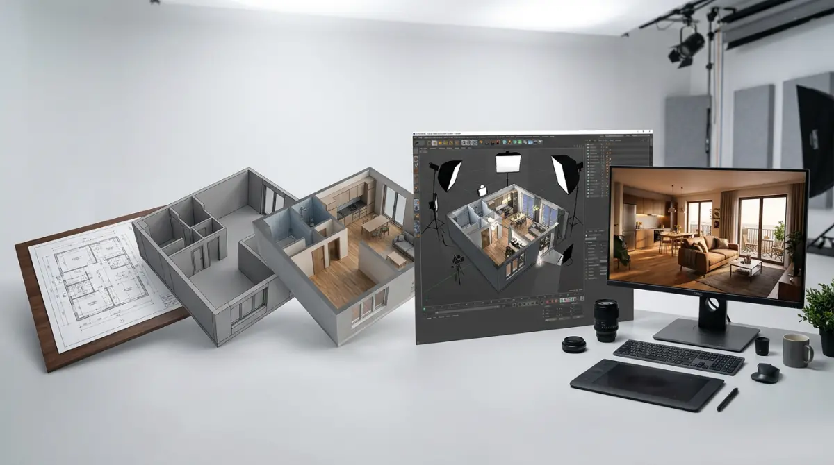
A lot of people treat this conversion as building a shell — four walls, a floor, a ceiling, some holes for doors and windows. That’s fine for a massing study. It falls apart the moment you introduce physically based materials and real lighting, because a shell doesn’t behave like a building when light hits it. What you actually need is a model that’s structurally honest at the geometry level:
- Correct scale — real-world units, consistent dimensions, an origin that doesn’t drift between floors.
- Clean topology — closed wall curves, no overlapping faces, no orphan vertices waiting to cause a snapping error three steps later.
- Watertight surfaces — enough continuity at corners and seams that light doesn’t leak through gaps you can’t even see in the viewport.
- Logical scene structure — walls, openings, floors, and ceilings as separate, named objects so materials and lighting can be art-directed independently.
- Rendering-ready shading — correct normals, deliberate bevels, predictable smoothing across large flat surfaces.
Your final render quality gets decided long before anyone touches a light rig. If the 2D source is ambiguous, that ambiguity becomes a 3D problem — just a harder one to spot, because now it’s hiding in a mesh instead of sitting on a flat page.
Picking a Software Pipeline for a 2D Floor Plan to 3D Model Conversion
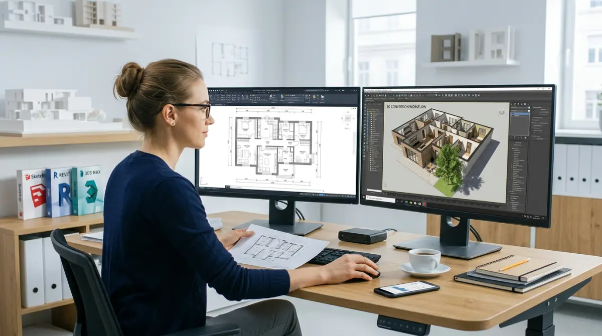
The right tool depends entirely on your output. Photoreal stills and animation want different handling than a lightweight AR preview. Most production pipelines are hybrid: BIM or CAD for accuracy and organization, then a DCC (digital content creation) application for cleanup, materials, and the actual render.
| Pipeline | Best For | What You Gain | Watch Out For |
|---|---|---|---|
| CAD vectors (DWG/DXF) → DCC (3ds Max / Blender) | Photoreal stills and animation | Direct control over geometry, UVs, materials | Needs proper cleanup before extrusion |
| BIM (Revit/ArchiCAD) → export → DCC | Projects with strong parametric data | Better structural organization and level alignment | Exports often carry heavy, messy geometry |
| SketchUp → DCC for final render | Fast early-stage visualization | Quick push-pull modeling, rapid iteration | Inefficient at scale; still needs cleanup |
| PDF/raster → vectorize → DCC | No CAD source available | Gets you into the pipeline from almost any starting point | Vectorization accuracy varies, needs manual correction |
For photoreal architectural work, the most dependable route we’ve found is importing cleaned vectors into a DCC tool, rebuilding walls and floors with controlled topology, then handling materials and lighting inside a physically based renderer. If AR or VR viewing is part of the final deliverable, decide your export format before you start modeling — it changes how you should build mesh density and UVs from the outset. The comparison in gltf vs usdz the best 3d model formats for ecommerce ar and vr is worth reading before you commit to a workflow.
Step 1: Clean the 2D Source Before You Model Anything
This is the step everyone rushes through because it feels like admin work, not design work. But you cannot build clean 3D geometry on top of ambiguous 2D data. The goal is a set of closed wall loops, or centerlines with consistent offsets, that you can extrude with confidence.
Strip out before importing: text annotations, dimension lines, leader arrows, furniture blocks, hatching patterns (these frequently import as dense overlapping geometry), and electrical/plumbing/HVAC callouts.
Z-plane discipline. If entities in your 2D file aren’t truly coplanar — even slightly — you get stray vertices on import. Those become snapping errors, micro-gaps in walls, and eventually light leaks. Confirm everything sits on one reference plane before extruding anything.
Scale — don’t estimate it. Working from a raster plan (JPEG/PDF)? Find a known dimension — a door width, a specified room length — and scale the image to match 1:1 in your scene. Working from DWG/DXF? Check unit settings at import; CAD files carry units inconsistently and your DCC tool may interpret them differently than intended. Always verify against a known measurement before extruding.
Curves and arcs. Vector sources beat raster every time for curved walls — raster loses arc fidelity fast. Keep segment counts high enough at import to avoid faceting after extrusion; you can always reduce density later, but an under-segmented curve never smooths itself out in the render.
Step 2: Extrude Walls With Real Openings, Not Boolean Guesswork
Once your layout is cleaned and scaled, extrusion itself is fast. What determines whether the render is clean or full of shading artifacts is how you handle wall thickness and openings.
- Use closed splines or polylines. Open curves produce broken or single-sided surfaces that will not shade correctly.
- Separate interior and exterior wall layers at minimum — different materials and thickness logic apply to each.
- Extrude to real-world heights pulled from the architectural spec, not eyeballed.
- Define door and window openings during extrusion, not after materials go on.
Boolean subtraction is fast for cutting openings, but messy input geometry produces non-manifold edges and broken loops almost every time. If your wall outline isn’t perfectly clean, manual polygon bridging around openings gives you far more control over edge flow and avoids inside-out faces that flip visibly under global illumination.
After extrusion, check your normals. Reversed normals are subtle in the viewport and glaring the moment GI kicks in, especially where walls meet ceilings. And don’t leave every corner at a mathematically perfect 90 degrees — real buildings don’t have those. A small, consistent chamfer at exterior corners and openings gives light something to catch, which is often the single detail separating a photoreal render from one that reads as obviously CG.
Step 3: Floors, Ceilings, and Keeping Multi-Story Buildings Aligned
Floors and ceilings are where light leaks are born or prevented. The most common mistake is floor geometry sitting slightly off the wall edges, leaving a gap you can’t see until path tracing turns it into a bright seam or shadow noise at the corner.
- Snap floor planes to wall outer edges — overlap or exact contact, either works, but be consistent across the scene.
- Align ceilings to the top of the walls for each floor.
- Avoid floating thin planes that don’t share vertices with walls unless your GI setup handles the gap reliably.
For multi-story buildings, model each level as a consistent unit and stack using the same reference origin. Eyeballing floor-to-floor heights introduces errors that are brutal to fix once materials and lighting are in — particularly where window reveals span two stories or a staircase needs to connect precisely. If your brief includes coffered ceilings, recessed lighting, or split levels, build those into the draft geometry now, not after texturing has started. For guidance on how much spatial detail to plan at each phase, the developer’s guide to 3d floor plan visualization for 2025 and 2026 is a solid reference point.
Step 4: Materials, Lighting, and Camera — the Rendering Stage
Once geometry is structurally sound, you switch from CAD thinking to rendering thinking. This is where PBR (physically based rendering) and accurate lighting carry the final image.
PBR and UV scale. Use at minimum a base color and roughness map, with normal maps for surface micro-detail on concrete, stone, or plaster. The single most common UV mistake in architectural work is getting texture density wrong — wood planks or tile patterns that read too large or too small make the whole scene feel like a dollhouse, no matter how good the render settings are. Use seamless textures and break tiling with variation masks or secondary detail geometry.
Lighting. The standard 2025–2026 approach for interiors is a natural daylight base — a physical sun and sky system or an HDRI environment — layered with artificial fixtures placed exactly where they exist in the design. Use IES profiles for spots and downlights wherever available; IES data matches real beam shapes and falloff, which kills the “too even” look that gives CG lighting away instantly.
Camera setup. Place cameras at believable eye height and correct vertical convergence. Most DCC tools have a two-point perspective or tilt-shift correction built in specifically for this. Converging verticals are one of the clearest tells that an image is a viewport grab rather than an architectural render — this single adjustment often matters more than any material tweak you make afterward.
What Clients Get Wrong: Real Production Observations
Raw CAD/BIM imports with no cleanup. Clients import a DWG or exported BIM file directly and hit render. What they inherit is duplicate vertices, overlapping faces, unnecessary tessellation running into millions of unnecessary polygons, and inconsistent normals. Rebuilding walls and floors with controlled topology in the DCC tool is almost always faster than trying to repair the mesh you were handed.
Scale errors that surface late. These don’t always look wrong immediately — they show up once you add furniture, compare a window to real-world proportions, or drop in a human figure for scale. Validate against a known dimension early. Measure a door width in both the source drawing and the 3D scene, and fix it before materials go on.
Light leaks from micro-gaps. If a wall and floor don’t share an edge properly, GI will find that gap and turn it into a faint bright seam. This is a geometry problem, not a lighting problem — no amount of light tweaking fixes a gap that shouldn’t exist.
Edges that are too sharp. Even when the design calls for crisp lines, renders generally need a small consistent bevel strategy. Razor edges with zero specular definition read as toy-like. A subtle chamfer gives materials the highlight behavior that makes them look real.
Treating draft geometry as production-ready. A basic layout communicates space fine, but marketing stills and walkthroughs need organized layers, named objects, and consistent material IDs. If the same model needs to serve stills, a walkthrough, and a web preview, invest in that organization from day one — it saves real time the moment a client requests a camera change or a material swap across every deliverable. The same principle governs quality outside architecture too — the relationship between modeling discipline and final image quality is covered well in 3d product modeling and rendering services how the modeling stage determines the quality of every final image.
Planning Ahead for Export and Format
Even if today’s deliverable is a handful of still renders, plan for reuse. Projects that start as marketing stills routinely expand into walkthroughs, web previews, or AR viewing later. If the scene wasn’t kept organized from the start — clean geometry, consistent materials, logical grouping — repurposing it becomes a rebuild instead of an export. Thinking about polygon budgets, material types, and texture compression during modeling, rather than after the model is locked, saves a lot of rework down the line.
Build It Right Before You Light It
| Pipeline | Best For | What You Gain | What to Watch For |
|---|---|---|---|
| CAD vectors (DWG/DXF) → DCC (3ds Max / Blender) | Photoreal stills and animations | Direct control over geometry, UVs, and material workflow | Requires thorough cleanup and careful extrusion logic |
| BIM (Revit / ArchiCAD) → export → DCC | Projects with strong parametric data | Better structural organization and level alignment | Exports can produce heavy geometry and messy topology |
| SketchUp → DCC for final render | Fast early-stage visualization | Quick push-pull modeling and rapid iteration | Large scenes become inefficient; cleanup is still necessary |
| PDF/raster → vectorize → DCC | Projects with no CAD source available | Gets you into the pipeline from almost any starting point | Vectorization accuracy varies; manual correction needed |
Converting a 2D floor plan to a 3D model in 2025–2026 is a pipeline, not a single operation. The results come from disciplined groundwork: clean vector sources, verified scale, properly extruded walls with real openings, aligned horizontal planes, and topology that’s actually ready for a renderer. Get the geometry right and lighting and materials behave the way you expect — you spend your time making the image better instead of chasing artifacts you can’t explain.
If you’d rather hand this off to a team that builds for final deliverables instead of draft previews, explore our 3d architectural rendering services, or contact us and we’ll help you plan the right pipeline for your project.
Frequently Asked Questions
What is the best software to convert a 2D floor plan into a 3D model in 2025?
For most workflows, a combination of AI-assisted tools like Maket.ai or Planner5D for automated wall detection paired with SketchUp, Revit, or Blender for refinement offers the best balance of speed and accuracy. Professional architects typically use AutoCAD to clean the 2D plan first, then import it into Revit or ArchiCAD for full BIM-based 3D modeling. The right choice depends on whether you need photorealistic rendering, BIM data, or quick visualization for clients.
Can AI automatically convert a scanned or hand-drawn floor plan into a 3D model?
Yes, modern AI tools like CubiCasa, Smart2D3D, and RoomSketcher can scan a raster image or PDF, detect walls, doors, and windows using computer vision, and generate a base 3D mesh within minutes. However, hand-drawn or low-resolution scans often require manual cleanup in CAD software afterward since AI accuracy drops with unclear lines or missing dimensions. This makes AI ideal for rapid drafts, but human verification remains essential for construction-grade accuracy.
What file formats are needed to convert a 2D floor plan to a 3D model?
The most common input formats are DWG, DXF, or PDF for vector-based plans, and PNG or JPG for scanned images, with DWG/DXF producing the most accurate 3D conversions due to precise vector line data. Output formats typically include OBJ, FBX, or SKP for visualization, and RVT for BIM-integrated projects. Choosing a vector-based input format significantly reduces manual tracing time during the modeling process.
How long does it typically take to convert a 2D floor plan into a detailed 3D model?
A simple residential floor plan can be converted into a basic 3D model in 30 minutes to 2 hours using AI-assisted tools, while a detailed, furnished, and textured model in Revit or 3ds Max may take 4 to 10 hours depending on complexity. Commercial or multi-story plans with intricate architectural details can extend this timeline to several days, especially when structural accuracy and BIM compliance are required.
What are the most common mistakes when converting a 2D plan to a 3D model, and how can they be avoided?
The most frequent errors include incorrect wall thickness, missing door/window swing directions, and scale mismatches caused by unclear or unscaled 2D drawings. These issues can be avoided by verifying dimensions against the original architectural scale before modeling and using layer-separated CAD files rather than flattened images. Running a quick cross-check between the 2D plan and the generated 3D model's floor area also helps catch proportion errors early.