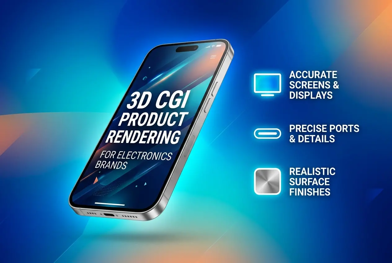
If you sell electronics, you already know the problem. The product exists on a CAD screen and in a factory schedule, but the engineering sample is weeks away, it has a visible tooling mark, or the colour is still being signed off. Meanwhile marketing needs a hero image, the crowdfunding page needs to go live, and the retailer wants listing assets. This is where 3D CGI Product Rendering Services for Electronics Brands: How to Get Accurate Screens, Ports and Surface Finishes Without a Prototype becomes a practical question rather than a theoretical one.
The short answer is yes, you can get convincing, accurate imagery without a physical unit. But electronics are unforgiving. A phone with a flat, grey-looking display or a laptop with the wrong port spacing looks fake in seconds, because buyers know exactly what these devices look like. Here is how we approach it in our studio, and what you need to hand over to get it right.
Why electronics are harder than most products
A sofa or a lamp forgives small errors. A router, earbud case or smartwatch does not. Electronics combine several difficult things in a single object: emissive screens, tight mechanical tolerances, tiny functional details like vents and ports, and a mix of materials that each react to light differently. Anodised aluminium, soft-touch plastic, glossy glass and brushed steel can all sit within a few centimetres of one another.
Add the fact that customers zoom in. Product pages let people inspect a USB-C port at full resolution. If the chamfer on that port is missing, or the inside is a flat black hole, the whole image loses credibility. That is why we treat electronics as a precision job, not just a “make it look nice” job.
Getting screens right
Screens are the number one giveaway. There are really two separate problems: what is displayed on the screen, and how the screen physically behaves as an object.
The content problem
Never let a renderer fill the display with a generic gradient unless that is your brief. We ask for the actual UI artwork, exported at the device’s native resolution and aspect ratio, ideally from your design team’s final files. If the UI is not finished, we agree on a placeholder, such as a neutral wallpaper or a lock screen, so the image does not date or mislead.
The physical problem
A real display is a stack: cover glass, optical bonding, the panel itself, and a black bezel border. We model that stack rather than just placing a flat texture on a plane. A few things matter a great deal:
- Emission versus reflection. A lit screen emits light, but the glass still reflects the room. Good renders show both. Too much glow and it looks like a sticker, too little and the screen appears switched off.
- Brightness balance. Camera exposure and screen brightness need to be matched, otherwise the display blows out to white or sits murky and dim. Photographers fight this constantly, and in CGI we control it deliberately.
- Pixel structure. For extreme close-ups, a subtle pixel grid or subpixel pattern adds realism. For normal shots, we avoid it because it creates moiré.
- Bezel and corner radius. The inner black border and the radius of the display corners are signature details. Get them off by a little and the product feels like a knockoff.
- Glass edge. 2.5D curved glass catches highlights along its edge. That bright rim is what tells the eye “this is glass.”
Ports, buttons and the small stuff
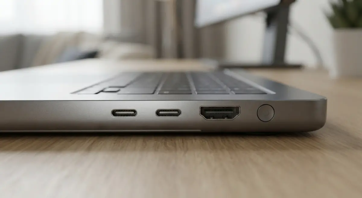
Ports are where CAD files and reality diverge most often. Engineering models are frequently simplified for manufacturing, so a connector might be a plain rectangular cut-out with no internal detail. For rendering, we need to know what a viewer will actually see.
When the source model is missing detail, we rebuild it. That means the metal shell of a USB-C opening, the tongue inside, the correct depth so the interior falls into believable shadow, and any visible gap between the port and the housing. Headphone jacks, SD card slots, speaker grilles and SIM trays get the same attention. A speaker grille, for example, is often delivered as a texture on the CAD side, but for a close-up we model or displace the holes so light actually passes into them.
Buttons deserve a mention too. Real buttons have a tiny gap around them, a slight height difference from the body, and a distinct material or finish. Those micro-gaps catch highlights and give the product physical weight. Remove them and the surface reads as painted on.
Surface finishes: matching materials without a sample
This is the part clients worry about most, and rightly so. If there is no prototype, how do you know the matte black will look like matte black? The answer is reference, and the more specific the better.
| Finish | What we need | What we build |
|---|---|---|
| Anodised aluminium | Colour code, finish name, any machining marks | Metallic base with fine anisotropic roughness and subtle edge wear control |
| Soft-touch plastic | Pantone or RAL value, gloss level | Low-gloss dielectric with micro-roughness and a faint sheen at grazing angles |
| Glossy polycarbonate | Colour and any texture beneath the clear coat | Layered clear coat over a coloured base |
| Brushed or textured metal | Brushing direction and grit | Directional roughness maps that follow the part geometry |
| Fabric or mesh | Weave sample or close photo | Tiled displacement with proper scale |
The best inputs are a CMF (colour, material, finish) sheet, a Pantone or RAL reference, supplier swatch photos, and even a similar existing product from another brand that shows the target look. We can also work from material data your manufacturer already uses, such as texture codes like VDI or Mold-Tech grades, which tell us how coarse the surface grain should be.
One habit we insist on: never judge a finish from a single lighting setup. Matte surfaces can look identical to satin ones in a flat studio light. We test materials under a few lighting conditions, including a strong side light, because that is where roughness differences become obvious.
What to send us, and what clients tend to get wrong
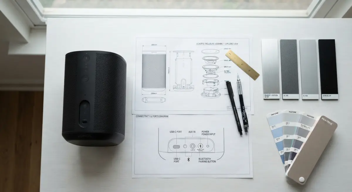
After enough electronics projects, patterns emerge. Here is what actually moves a job forward smoothly.
- Send the right CAD. A STEP file from engineering is a good start, but tell us whether it reflects the final design. Outdated geometry is the most common cause of rework.
- Share dimensions for verification. We check the model against a spec sheet, so buttons, ports and screen size match the real thing.
- Decide on screen content early. Last-minute UI changes mean re-rendering. Locking this down saves everyone time.
- Do not expect CAD to be render-ready. Engineering models are heavy, full of internal parts, and usually lack bevels. Real products have tiny edge radii that catch light. Sharp CAD edges look like clay models until we add them.
- Be honest about the approval stage. If the design may still change, say so. We can build the scene so updates are quick, with swappable colours, screens and materials.
The biggest mistake we see is treating accuracy and beauty as opposing goals. They are not. A render that respects the real part gaps, real finish and real screen behaviour also looks more premium, because the human eye reads those details as truth.
Beyond the hero shot: reusing the same scene
One real advantage of working this way is that the 3D asset keeps paying you back. Once the product is built and textured, the same model supports colour variants, exploded views showing internals, lifestyle scenes, packaging shots and even animation. When the physical prototype finally arrives, you can compare it against the render and tweak the digital version if the factory finish drifted slightly. If you are planning launch videos, our 3D product animation services can reuse the same model for turntables and feature callouts.
Final thoughts
Accurate electronics imagery without a prototype is absolutely achievable, but it depends on specifics: real screen artwork, a screen modelled as layered glass, ports rebuilt where CAD is lazy, and finishes matched against proper references instead of guesswork. Done well, nobody can tell whether the product was photographed or built in software, and you can launch on your schedule instead of the factory’s.
If you have a product in development and need launch-ready visuals, take a look at our 3D product rendering services, or send us your CAD and spec sheet through our contact page. We will tell you honestly what is workable from the files you already have.
Frequently Asked Questions
Can a 3D CGI studio render my electronics product accurately before a physical prototype exists?
Yes. Studios can build photorealistic renders directly from your CAD files (STEP, IGES, or SolidWorks), engineering drawings, and material specs. The renders are only as accurate as the data you supply, so final dimensions, port locations, and finish callouts should be locked before modeling starts. Many brands use these renders for pre-launch marketing, crowdfunding, and retailer listings months before production units are ready.
How do 3D artists make device screens look realistic in product renders?
Artists apply your supplied UI mockups or lifestyle imagery as emissive textures, then add details like glass reflections, subtle bezel shadows, and accurate display brightness. They also match aspect ratio, corner radius, and pixel-level characteristics to the real panel. Screen content can be swapped without re-modeling, which makes it easy to produce multiple regional or feature-specific versions.
What information does a rendering studio need to model ports, buttons and connectors correctly?
Provide the CAD model with internal tolerances intact, plus reference photos of comparable components such as USB-C, HDMI, or SIM trays. Specify the dimensions, depth, and any internal details visible from outside, such as metal contacts or plastic tongues. Clear labeling of button travel, LED positions, and vent patterns helps ensure close-up shots match the production unit.
How are surface finishes like anodized aluminum, matte plastic or glossy glass recreated in CGI?
Studios use physically based rendering (PBR) materials that control roughness, metalness, reflectivity, and micro-texture to replicate each finish. Reference data such as Pantone or RAL codes, CMF (color, material, finish) specs, or physical material swatches lets artists match the look closely. Lighting setups and HDRI environments are then tuned to show anodizing grain, soft-touch diffusion, or glass reflections accurately.
How much does 3D product rendering for electronics cost compared to traditional product photography with prototypes?
Pricing typically depends on model complexity, number of images or animations, and resolution, with a single hero image often costing less than a full photo shoot with logistics and retouching. After the model is built, new angles, colorways, and variants are inexpensive to produce, while photography requires reshoots. CGI also avoids the cost and delay of building prototypes purely for marketing imagery, which gives it strong ROI for brands with multiple SKUs.