A founder emails us with a sketch, a rough spec sheet, and a deadline for a trade show that’s six weeks out. The tooling quote from their manufacturer alone is enough to make anyone nervous — injection molds aren’t cheap, and once cut, they don’t forgive a bad decision about wall thickness, a misjudged proportion, or a color that looked fine on screen but wrong in person. This is exactly the situation where 3D product design rendering earns its keep. Before a single dollar goes into tooling, we can build a fully dimensional, photoreal version of the product that lets the whole team — designers, investors, manufacturers — look at the thing as if it already exists. That’s the real value of 3D product design rendering: how to visualise a product concept before you commit to tooling, catch the mistakes early, and walk into production with confidence instead of a hopeful guess.
I’ve been doing this long enough to know that most product failures aren’t failures of the idea — they’re failures of communication. A designer sees the product one way in their head, the CAD engineer builds it slightly differently to make it manufacturable, and the marketing team is trying to sell a version that doesn’t quite match either. Rendering forces everyone to look at the same object, lit the same way, from the same angle, and agree on it before the mold steel gets cut.
This post is for anyone sitting at that pre-tooling stage — physical product founders, industrial designers, hardware startups — who wants to know what rendering can actually do at this point in development, and what it can’t.
Why Tooling Is the Point of No Return
Injection molds, die casts, and vacuum forms are expensive precisely because they’re inflexible. A steel mold cavity is machined to a tolerance of fractions of a millimeter. Once it’s cut, changing a wall thickness or a fillet radius often means cutting a new mold, not adjusting the old one. Some changes can be patched with inserts or welding, but anything structural usually means starting over.
This is why the smartest product teams push as much decision-making as possible into the digital phase. A rendering error costs you an afternoon of revision. A tooling error costs you weeks and a fresh invoice from your manufacturer. The math isn’t close.
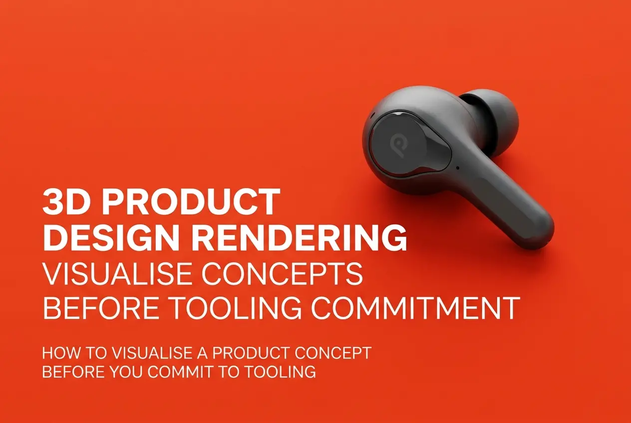
3D Product Design Rendering: How to Visualise a Product Concept Before You Commit to Tooling
At its core, this process takes your CAD model — whether it’s a rough SolidWorks file, a Rhino surface model, or even a hand sketch we convert into 3D — and builds a photoreal representation of the finished product. Materials, lighting, reflections, texture, scale, all rendered as if photographed in a studio. It’s not a drawing of your idea. It’s a visual proof of your idea, accurate enough that you could put it next to an actual photo of the finished product and most people wouldn’t be able to tell which is which.
We usually break this into three stages when working with product teams:
1. Concept Visualization
Early on, before the CAD is even locked, we render multiple design directions — different housing shapes, button placements, color options — so the team can compare them side by side. This is cheap to do in 3D and prohibitively expensive to do with physical prototypes for every variation.
2. Engineering Validation Renders
Once CAD is closer to final, we render the model with attention to actual manufacturing constraints — draft angles, parting lines, wall thickness variations that will show up as sink marks in real plastic. A good rendering artist who understands injection molding will flag these issues before they become tooling problems, not after.
3. Marketing-Ready Renders
Once the design is locked, we produce the final hero shots — the images that will actually go on the crowdfunding page, the retail listing, the investor deck. These often get built using the same 3D product rendering services pipeline that generates catalog and packshot images later, so there’s no wasted work.
What Rendering Actually Catches Before Tooling
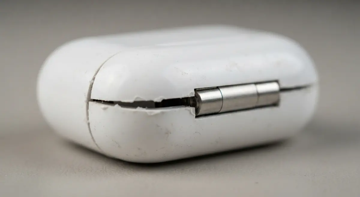
Clients are often surprised by how much a good render reveals that a CAD viewport hides. CAD software shows you geometry. It doesn’t show you how light behaves on that geometry, and light is where most design flaws become visible.
| Issue | How CAD Hides It | How Rendering Reveals It |
|---|---|---|
| Surface transitions | Flat shading smooths everything visually | Studio lighting shows every ripple, bump, or awkward blend between surfaces |
| Proportions | Default camera angles distort scale perception | Human-scale reference and realistic framing show true proportion |
| Material choice | Generic gray or default color material | Actual material shaders show if a matte plastic will look cheap, or if brushed aluminum reads as intended |
| Color accuracy | Screen color settings vary widely | Rendered under calibrated studio HDRI lighting matches real-world expectations more closely |
| Assembly gaps | Parts can overlap invisibly in CAD | Rendering with real-world tolerances shows visible seams and gaps |
We had a project where the CAD model looked completely fine — a small consumer electronics housing with a soft-touch finish. But once we rendered it with an accurate soft-touch rubber shader under angled studio lighting, a subtle warp in one of the side panels, invisible in the flat CAD viewport, suddenly showed up as an obvious dip. That kind of thing is nearly impossible to catch until you either build a physical prototype or render it properly. Rendering is far cheaper and faster than the former.
Material and Finish Decisions Before You’ve Bought a Single Sheet of Material
One of the most underused strengths of rendering at this stage is testing finishes without committing to them physically. Should the housing be matte or gloss? Brushed metal or anodized? Should the accent color be a warm gray or a cool one? These decisions affect manufacturing cost, and testing them physically means ordering samples, waiting on shipping, and often discovering the sample doesn’t match what you imagined anyway.
In a render, we can produce the same product in six finish variations in the time it takes to physically test one. This isn’t about replacing physical prototyping entirely — it’s about narrowing the field before you spend money on physical samples, so the ones you do order are the ones with a real shot at being final.
Where Rendering Fits Alongside Physical Prototyping
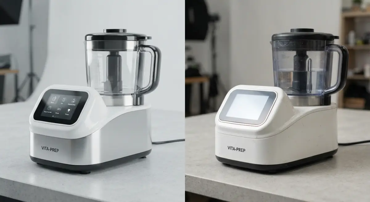
I want to be clear that rendering doesn’t replace physical prototypes. It replaces the wasted iterations before a physical prototype makes sense. A 3D print or a machined aluminum sample still tells you things a render can’t — how it feels in the hand, whether the button click has the right resistance, how it holds up to drop testing. Rendering answers the visual and proportional questions; prototyping answers the tactile and functional ones. Teams that skip rendering and go straight to physical prototyping often burn through three or four prototype rounds fixing things that a render would have caught in the first pass. Teams that skip physical prototyping entirely and trust renders alone sometimes get surprised by how a form feels once it’s actually in someone’s hand. The correct order is: render first, prototype to confirm, then tool.
What Clients Get Wrong at This Stage
A few patterns come up often enough that they’re worth naming directly.
Clients sometimes send us CAD that hasn’t been checked for manufacturability and expect the render to “fix” it visually. A render can’t hide a design flaw — good lighting actually exposes flaws more than it hides them. If a part has an awkward proportion, rendering it beautifully will just show everyone a beautifully lit awkward proportion.
Another common mistake is rendering too late. Some teams wait until CAD is fully locked before requesting any renders, thinking it’s a final-stage marketing task. By then, the tooling decisions are basically made, and the render becomes a documentation exercise rather than a decision-making tool. The earlier you bring rendering in — even with rough, unfinished CAD — the more money it saves you down the line.
And occasionally, clients want the render to be more forgiving than reality will be — asking us to soften a seam or hide a parting line that will absolutely be visible on the actual manufactured part. We push back on this. The point of a pre-tooling render is accuracy, not flattery. If we make it look better than it will actually look once molded, we’ve just moved the surprise from the design phase to the production phase, which is the opposite of what this process is for.
A Practical Workflow We Recommend
For teams heading toward tooling, here’s the sequence that tends to work best in our experience:
- Send CAD as early as possible, even in rough form, alongside any material or finish preferences.
- Request concept renders for any design decision still open — color, texture, minor form variations.
- Once a direction is chosen, request engineering-aware renders that account for actual manufacturing constraints like draft angles and wall thickness.
- Review renders under multiple lighting setups, not just one flattering studio shot — a product that only looks good under one light angle is a red flag.
- Use the final approved renders as the reference standard your manufacturer works against, reducing back-and-forth during first-article inspection.
This same asset set often gets reused afterward for the product page, the crowdfunding campaign, or the retail listing — so the investment doesn’t stop paying off once tooling starts. It’s worth treating your rendering budget as part of your product development cost, not just your marketing cost, because that’s really what it is doing at this stage.
If you’re sitting on a CAD file and a tooling quote and want a second set of eyes before you commit, that’s exactly the kind of project we like working on. Get in touch with our team through our 3D rendering services contact page and send over your files — we’ll tell you honestly what we see, tooling risks included.
Frequently Asked Questions
How much does 3D product design rendering cost compared to building a physical prototype?
3D rendering typically costs a few hundred to a few thousand dollars depending on complexity, while physical prototypes and tooling can run into tens of thousands of dollars. Rendering lets you test and revise designs digitally before committing capital to molds or manufacturing setup, making it far more cost-effective for early-stage validation.
What is the difference between 3D rendering and CAD modeling for product design?
CAD modeling creates the precise technical geometry and dimensions used for engineering and manufacturing, while 3D rendering applies materials, lighting, and textures to that geometry to produce photorealistic visuals. Rendering is typically used for marketing, stakeholder buy-in, and design review, whereas CAD is used to prepare files for tooling and production.
Can 3D renderings accurately predict how a product will look before tooling begins?
Yes, high-quality 3D renderings can simulate real-world materials, finishes, and lighting conditions closely enough to preview color accuracy, surface texture, and proportions before tooling. However, they should be paired with accurate CAD data and, ideally, a small-scale 3D print or prototype to confirm ergonomics and fit before finalizing tooling investment.
How long does it take to create a photorealistic 3D product rendering?
A single photorealistic rendering typically takes anywhere from a few days to two weeks, depending on model complexity, number of views, and revision rounds. Simple products with existing CAD files can be rendered faster, while intricate designs with custom materials or multiple color variants require additional time.
What file formats do I need to provide a designer for 3D product rendering?
Most 3D rendering studios require native CAD files such as STEP, IGES, or SolidWorks formats to ensure accurate geometry. If you don't have CAD files yet, designers can often start from sketches, reference images, or rough dimensions, though this may require an additional 3D modeling phase before rendering begins.